Fusion 360 Tutorial: 3D Modeling for 3D printing with Fusion 360

Summary​

Modeling for 3D printing requires attention to a number of optimal practices.

First, there is an inherent limit to the mechanical properties of the materials used in these limits which can be tested using the software simulation model. It is also important to take into account that the created file will be a virtual representation that allows 3D printers to create a physical object.

In this part, you will see the key points to create a suitable model with Fusion 360 for 3D printing.

Note that we distinguish in CAD two types of modeling: parametric modeling and direct modeling.


Parametric modeling (design for functional parts)

Parametric modeling is suitable for the modeling of parts with functional geometries (mechanical parts, such as a gear, for example). Models are then further refined by parameters which can be easily modified.

Freecad, Soliworks and Catia are parametric modeling software (rather engineering oriented). 

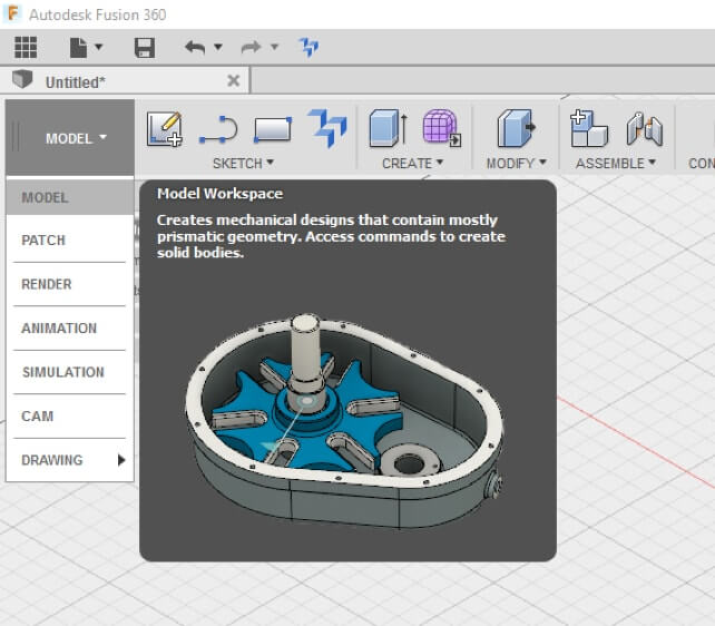
There is the Model workshop, which allows one to draw a sketch in a two-dimensional plane, which can then be transformed to 3D with the volume creation operations. It is also possible to directly create volumes (cube, cylinders, spheres …) without going through the sketch.

F360 1.1 1.jpg


The Model workshop contains assembly functions.

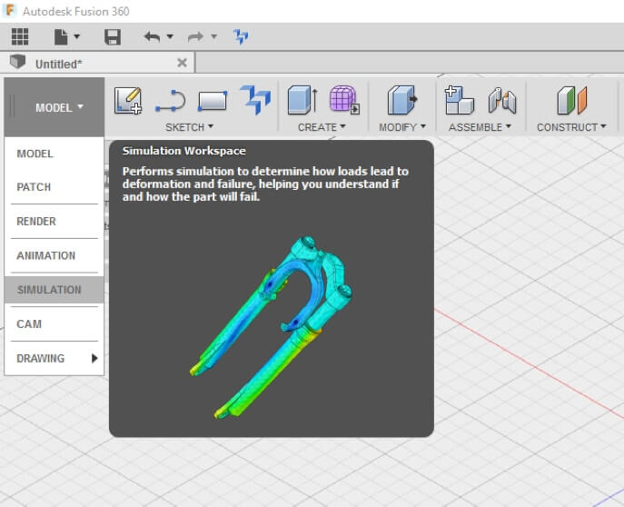
The Simulation workshop is particularly useful especially for functional parts. This workshop is used for measuring the mechanical strength of the materials against predetermined constraints. Because in addition to the material thickness specifications, minimum strength and thickness concepts of each individual component must be taken into account according to users modeling.

F360 1.1 2.jpg 


Direct Modeling (Design for Aesthetic Parts)

Direct modeling offers more flexibility in terms of creativity and aesthetics. In fact, by manipulating curves and surfaces one can obtain very beautiful pieces with complex and organic shapes.

This is a so-called surface modeling, as on other software like Rhinoceros , for example. 

Fusion 360 operates on a spline system ( curves passing through fixed points), and more precisely T-spline. The fundamental difference between T-splines and NURBS surfaces is the presence of star points. The star points allow to create non-rectangular polygons and thus very complex curved surfaces by limiting the quantity of polygons on the mesh. 

However, one possible disadvantage of direct modeling is that the parts created are not necessarily functional because of the direct modeling approach (organic shapes). 

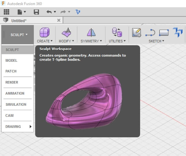
The Sculpt workshop allows users to sculpt by drawing curves on the basis of T-Splines. We then move in 3D with volume creation operations; Create >  Extrude / Revolute …”.

F360 1.1 3.jpg 

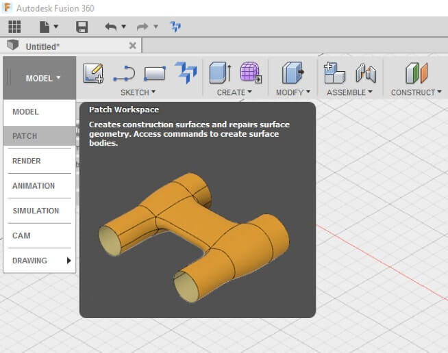
Then there is the Patch workshop which allows the user to close and delineate the surfaces,

with the aim of creating volumes.

F360 1.1 4.jpg 

One major advantage of Fusion 360 is that it can transition from the surface module to the volume module very quickly.


Some important rules to respect in modeling:

  • All modeled elements must have a thickness to be 3D printed. A surface on a CAD software doesn’t have a thickness, to obtain it, your part must have an “ inside ” and an “outside
  • Your part (object) must be watertight, that means it must have an « inside» and an « outside » but as Fusion 360 isespecially designed for 3D printing, you will see that it causes very few errors
  • The different elements of your modeling should not intersect
  • Your file must be less than 50MB after export. This limit is usually sufficient to generate a valid file for printing without losing details or information. We will outline how to export your files and manage file size in the chapter devoted to exporting your model
  • While it is possible to export several bodies in a single valid STL file, it is optimal to maintain fidelity of your model by creating and exporting each component individually

Christmas is coming soon, it is thus necessary time to make your own candle holder,  for the decoration of your Christmas tree, for example.

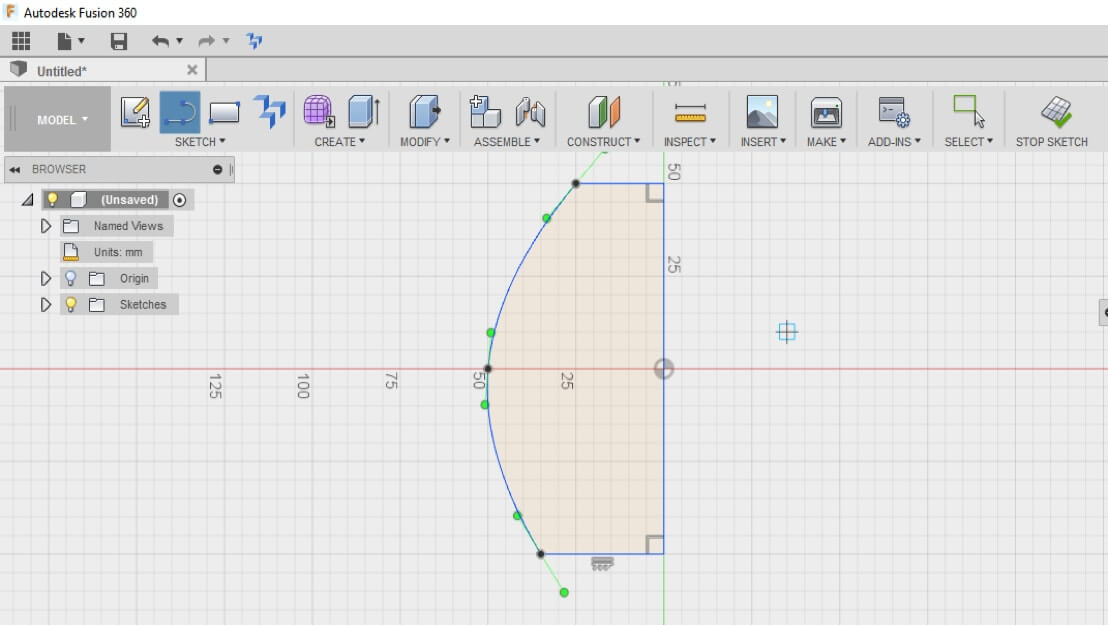
Begin your sketch by using the tool splines in the sketch menu. Then close your surface.
F360 1.1 5.jpg

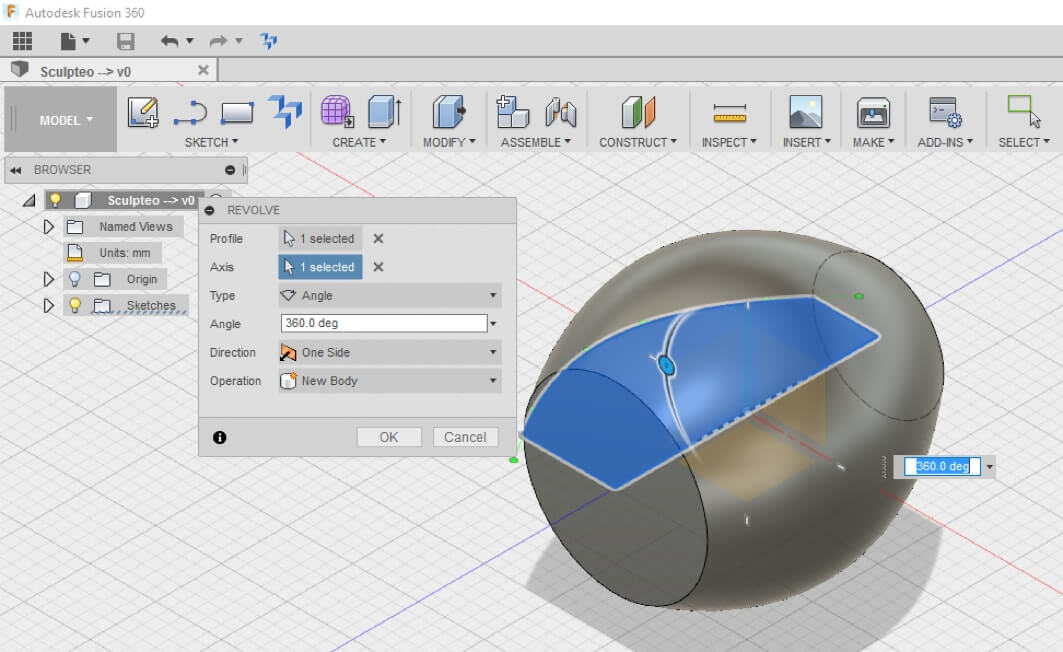
Create then a volume with an operation of Revolution, in the workshop Create.
F360 1.1 6.jpg 

To create the base on which will be positioned the candle, it is necessary to separate the body in two bodies, using the function Offset Plane.
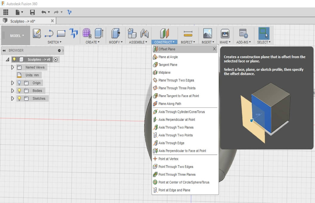
F360 1.1 7.jpg

Then, in the Modify Menu, select the Split Body tool.
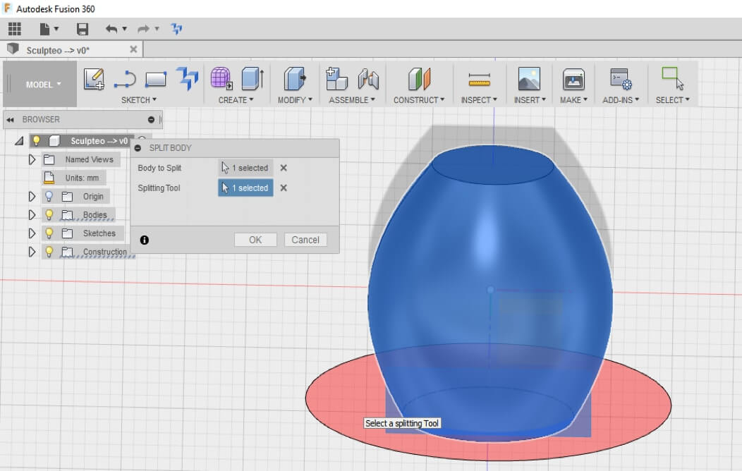
F360 1.1 8.jpg

You can now see two different bodies. But be careful, if you wish to print separately the two bodies, it is necessary to transform them into two separated components. 

NB: Even if 2 bodies are different, they will be printed as a single component. As evoked previously, if you wish to print in various materials these two bodies, it is necessary to transform the bodies into two separated components. 

To modify the appearance, right click on the body (Appearance), then select the desired material. This is only for the visual appearance: the choice of the material to take into account the mechanical resistance is made in the Simulation workshop.
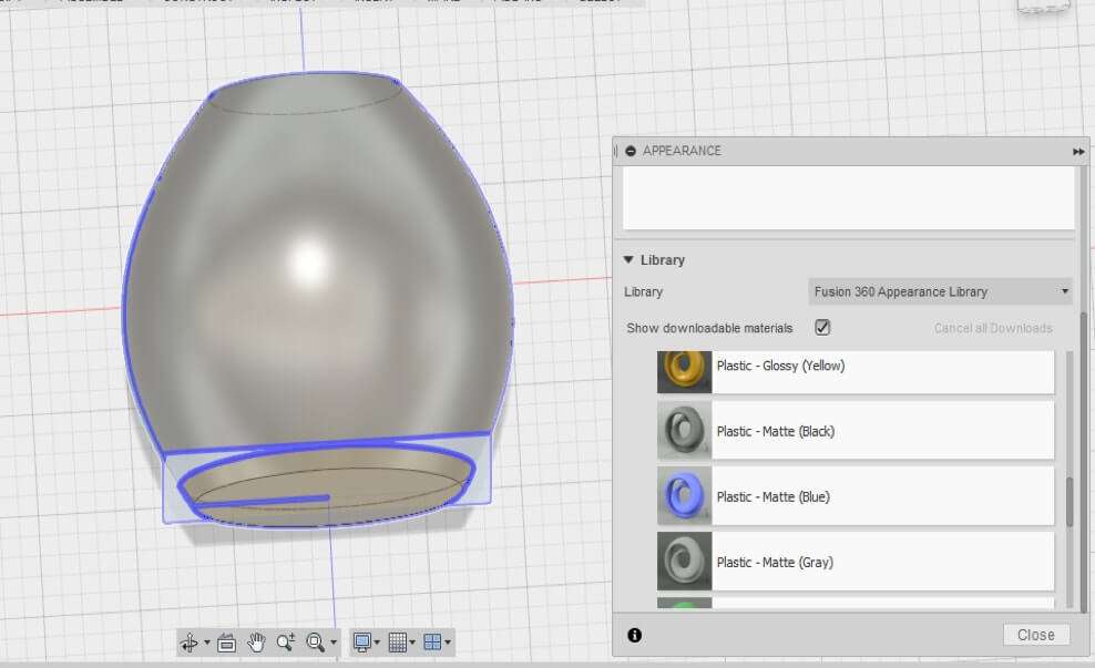
F360 1.1 9.jpg

Uncheck the second created body (the base), by marking in the arborescence of modeling the yellow light which becomes then white. Then use the function Shell to give a thickness to the body #1.
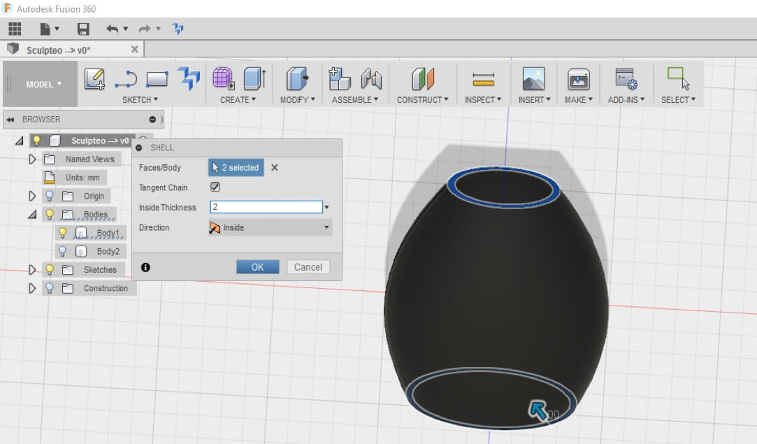
F360 1.1 10.jpg

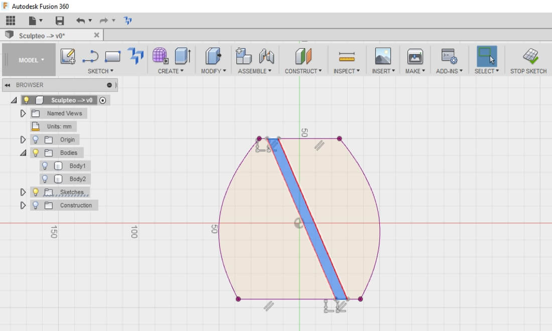
Recreate a new sketch, and throw the view on the same plan as the very first created sketch (SKETCH → PROJECT). 

Draw then a rather fine strip, then extrude this strip according to the normal for the plan, and symmetrically with regard to the plan.
F360 1.1 11_5Pu02iv.jpg

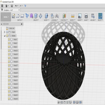
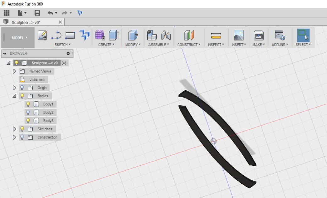
Create then the intersection between the 1st created body and the new created volume. You obtain then this body. 
F360 1.1 12.jpg

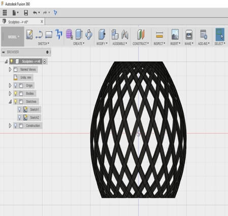
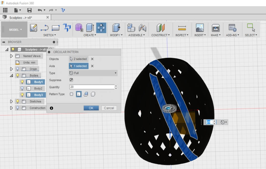
Reproduce this shape, with the Circular Pattern tool. You can determine the number of desired bodies, which will impact directly on the luminosity emanating from your candle holder. 
F360 1.1 13.jpg

F360 1.1 14.jpg 

F360 1.1 15.jpg

Your candle holder is now ready for 3D printing. You can from now upload it on Sculpteo.


Simulation Workshop

In our case, a simulation of the mechanical resistance of the part and the weak spots is not a very useful study because of the very light weight of a candle.

Nevertheless, it can be interesting just to test the Simulation workshop

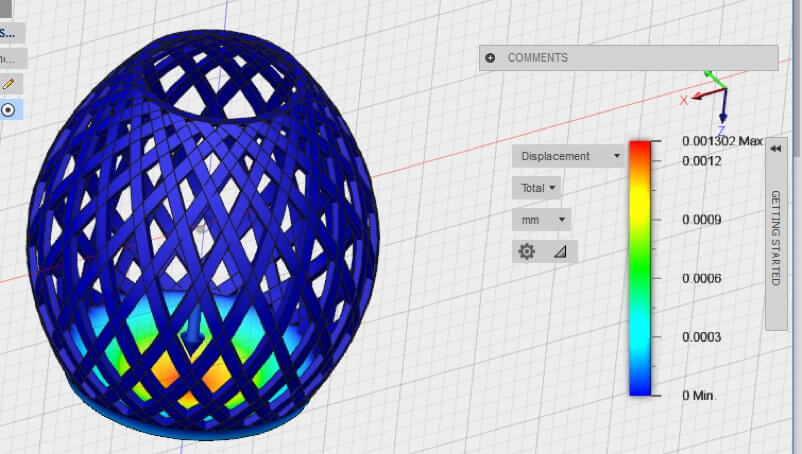
Go to the module Simulation and select the desired material. 
F360 1.1 16.jpg

We selected here some Polyamide (PA12) material, often used in SLS 3D printing. We apply a load of 5N (that is the strength of the weight of a candle of 500g, if we applicate the physical formula W = m * g, g being the gravitational acceleration and whose the value is around 10). After solving, we can immediately locate the most fragile zones (in red).